75ZT Community
A social community of enthusiasts, owners, appreciators and collectors. With expert knowledge of all things from MG to Rover and beyond.
Clock module to give arrival time by Duncan (Page 3 of 6)
You have an email for 1 fully built please! It does work with MK3?
I'm a little worried. I've had communication from the first two people to fit their modules, that they don't work. This worries me, because I have fully tested each one, more than once, before I shipped them. It seems that they are connected right, too.
Now I tested them on a bench setup with the satnav module, TV tuner, radio module and instrument pack. I think I've found an error in a component value that would explain why it would work on my test setup, but not on a car with a complete kbus setup. However I need to check this out which I need a clearer head to do than I have right now. If I'm right it will be a fairly simple fix, but I do need to do some measurements and tests first.
I apologise for this, and should have known better than to rely on a bench test. I'm forever telling my suppliers who tell me 'it works on the bench' that we 'don't sell benches' and now it seems I might have fallen into the same trap. I thought it should be straightforward being based on an existing design, but if I can't read resistor colour codes right, I'm looking for an epic fail!
I will try to test this tomorrow, but can't promise this as I'm a car down needing brake work. I will sort this and work out how to fix it, if indeed it is down to this! Sorry, in advance.
Thanks for the update,
Not got round to fitting mine so will await further updates.
Not got round to fitting mine so will await further updates.

Just to explain a bit. It seems I misread the value of a resistor on the original circuit as 1000 ohms when it should be 100 ohms. This would explain why it works 100% on my test rig, but not on cars that have more things connected on the kbus. I will know for sure before the end of the weekend, and propose a solution. Whatever the outcome I will sort this out.
Great - just got in from trying to fit mine, but no success, I thought it was me! Thanks for the info
Now some good news. I've been unable to check it out other than confirming the original has 100 ohms, where I read it as 1000. Terry (tez75) however has changed the resistor on his board, and proved that with 1000 ohms it doesn't work on a car (although it works with the satnav bits on a bench) but swapping it for a 100 ohm resistor and it works fine. Many many thanks Terry, I'm grateful more than I can say.
I have some resistors on order, so have to figure out the best way to get the modules repaired. I'll PM or email each of those who have one, to discuss what is the best way for each of you. Thanks for your understanding on this.
I have some resistors on order, so have to figure out the best way to get the modules repaired. I'll PM or email each of those who have one, to discuss what is the best way for each of you. Thanks for your understanding on this.
I'm posting the installation instructions, even though you can't fit them yet. That's because I will also use the photos when I email and PM each of you to discuss options for sorting out my error.
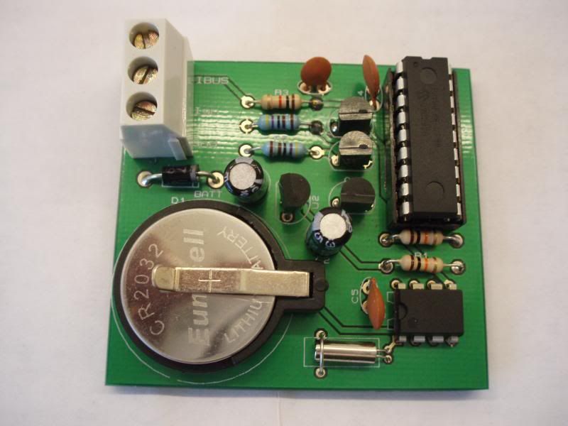
First a picture of the PCB (Printed Circuit Board) as you have received it:

You can see there are three screw terminals, marked Ign, Gnd, and kbus (not in that order). You can connect anywhere you like, but there's a couple of places to consider. One is in the wheel well, but if you have a car that originally had a Mk3 then above the satnav unit is probably easier. Whichever, the connections are the same. If the car has had a Mk2 you can use the connection that used to go to the GPS receiver. Otherwise tap into the wires that go to the back of the radio on the right of the wheel well, or the wires that go into the back of the satnav module. Gnd is connected to the plain black wire, Ign is connected to the light green with white stripe wire. Kbus is connected to the white wire with red stripe and yellow dots. It's important not to connect the ign wire to a permanent live as it will stop your kbus going to sleep and flatten your battery.
I recommend putting a 1A fuse in line with the ignition wire.
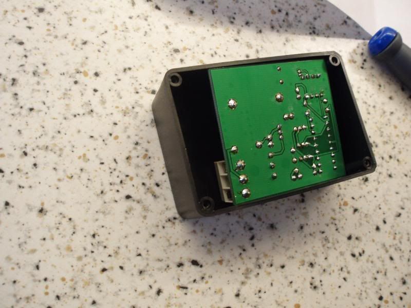
Don't forget to put a hole in the side of the box and feed the wires through before connecting up. Once you have, you may forget which way the board goes in. Here's a photo showing you. It is tight, but it kept the box small, and it won't rattle!

First a picture of the PCB (Printed Circuit Board) as you have received it:

You can see there are three screw terminals, marked Ign, Gnd, and kbus (not in that order). You can connect anywhere you like, but there's a couple of places to consider. One is in the wheel well, but if you have a car that originally had a Mk3 then above the satnav unit is probably easier. Whichever, the connections are the same. If the car has had a Mk2 you can use the connection that used to go to the GPS receiver. Otherwise tap into the wires that go to the back of the radio on the right of the wheel well, or the wires that go into the back of the satnav module. Gnd is connected to the plain black wire, Ign is connected to the light green with white stripe wire. Kbus is connected to the white wire with red stripe and yellow dots. It's important not to connect the ign wire to a permanent live as it will stop your kbus going to sleep and flatten your battery.
I recommend putting a 1A fuse in line with the ignition wire.
Don't forget to put a hole in the side of the box and feed the wires through before connecting up. Once you have, you may forget which way the board goes in. Here's a photo showing you. It is tight, but it kept the box small, and it won't rattle!

Clock module arrived all ok. Tested it yesterday and not a lot happened!! At the bottom left of sat nav screen I have '45:00', which never changed, no date or time appeared. In the 'computer' option from main menu the outside temp. was there, nothing else. Now, switched car off, left for 15mins and then restarted. Nothing!! Temperature blank. Not even the mysterious '45:00'!! Any ideas? I have MK3 running V32, BM24 and 4:3. T4 (Testbook version 4.Computer Diagnostic System) session required? The sat nav was not factory fit and as far as I can recall has never been enabled? Sounds likely?
wihile this may not help.the previous units made by hans had a few issues caused by folks using to thick a wire to make the connections.i used a section of old 75 roof loom.
May be a Mk3 thing, fitted mine and the new resistor yesterday. now the time appears at the lower left hand side of the screen. Nothing else though? I will look at setting the clock but as it is automatically showing the correct time i assume its doing what it should in that dept.
Welcome to all who have managed to migrate 
Dave....
Dave....
OK thanks guys, I'll give it another go. I am wondering though if a T4 session to enable sat nav will do the trick? Will report back.
Can't set the clock, well it wont save time?
Duncan wrote:Regarding the arrival time. My understanding is now you have the time displayed, once you set a destination in the navigation you will get the eta shown in the nav display.
tryed the sat nav no eta stil very pleased with tho.some if i remember had to use a thing called a ressler interface and a programme called navcoder to get this function to work
OK. Tried it again with no results. Hooked up a separate 12V supply and connected Kbus, left car for 15 mins switched on and nothing. Have got the Ressler and Navcoder so will give that a go. Other than that any other suggestions??
OK Scott. With the navcoder, check if you are getting messages sent by the clock module. There should be one roughly every minute from quick observations. I'm pretty sure I checked your module on my car before I sent it so I think there's something else amiss here. If it won't save the time, the clock module isn't talking to the car.
Regarding coding with Navcoder, I haven't looked into it. When I first bought a clock from Hans, it didn't work as mine was a Rover Mk3 not a BMW. I'll dig a little deeper, but I do have Navcoder as well.
Regarding coding with Navcoder, I haven't looked into it. When I first bought a clock from Hans, it didn't work as mine was a Rover Mk3 not a BMW. I'll dig a little deeper, but I do have Navcoder as well.
Hello Duncan, put me on the list for a full build one. It's for a MK4, formal BMW, 16:9 screen.
Please pm me the total costs, including the postal cost to Belgium.
Regards, Yosh
Please pm me the total costs, including the postal cost to Belgium.
Regards, Yosh
"Murphy is an optimist".
Law of Mulder.
Law of Mulder.
Hooked up Navcoder and had a look, no signal appears to be coming from the module. I'm still wondering if a T4 session would help?

